Sunday, October 26, 2014

Back on The Bottom!

     Since finishing grad school, my free-time has opened up dramatically; however, I have since taken on a project fabricating new brightwork and painting a sailing dinghy (see www.awee1.blogspot.com)....so my time on the W32 has been spare to none!  Well, I have determined to hold myself to at least some amount of time per day to establish the needed "momentum" to complete the build-out....and at least while the W32 is in my possession.  You see, I am at a bit of a cross-roads:  either keep and complete this W32, or....fulfill this nagging desire to own and sail a W42.  Only time will tell which path I follow...I have put a lot in this project thus far (time and money), so my decision needs to be made soon.

Anyway, sticking to the commitment I made to myself, and with daylight burning, I managed to get 1/2 an hour on the starboard bottom sanding.  


Using 80-grit PSA pads on the Porter-Cable 7335, 6" pad, I prepared half of the starboard side for its inevitable 120-grit pass.  With light fading fast, I wrapped things up with "at least some amount of time" spent on the project.  Cheers!


Total Time: .5 hours

Monday, January 6, 2014

Mast Compression Block Install


After final preparations were made to the mast compression block (laminating, wrapping in cloth, fairing minor imperfections), I got around to installing it Sunday, the 5th of January.  The mast compression block would be the final leg of a vertical structure taking the mast load to the keel.  The block measures 6" x 6" x 4.5", a cube, and is laminated in construction; it consists of 4 1/2" thick solid fiberglass sheets, an 8/4" thick teak block, and a 1/2" thick block of purpleheart.  With some last minute trimming of the port mast bulkhead to bring in line with the underside of the floor timber, I vacuumed all surfaces and wiped down with solvent to prepare for the installation.


Placing the solid block into position, I took some measurements for length of cloth (1708 biaxial) and generally preparing for the installation - rehearsing the install mentally so as to avoid unnecessary complications.


The dry-fit from overhead shows good position for the block to accept a distributed load from the floor timber.  A final section of the floor timber will go in after this installation of the mast compression block.  For the picture below, the final 3/4" thick meranti board will be attached to the existing floor timber on the forward side (the upper portion of the picture).  This final section of the floor timber will serve to accept the forward sole substrate.


The dry-fit of the mast compression block standing forward of the floor timber, looking aft from the starboard side...


...and a final picture of the dry-fit from the port side.


Satisfied with the mast compression block's dry-fit, I went ahead and measured for the cloth needed for the installation.  Only one length of 1708 biaxial would be used for this initial bonding in of the compression block, the balance of the pieces would be used to clean up the uneven glass in the forward portion of the salon's bilge.  There were voids that I wanted to fill and clean up in this area.  The glass cut list, shown below, is sitting in the referenced area. 


With final preparations made, I moved the epoxy dispensing system to the boat and set-up a work area for mixing and saturating the cloth.  First step was to mix a small amount of the epoxy to wet-out the work area.


Another shot of the work area prepped for further work.


With the temperature in the mid-70s, I work feverishly through the bonding process to ensure maximum working time before batches of epoxy began to cure - time is money when it comes to working with epoxy!  So, as a result of my frantic pace, I took no pictures of the bonding process.  The remaining pictures show the completed installation of the mast compression block.  Wet cloth can be seen standing  proud of the top of the floor timber, and this will be ground off after it fully cures.  The picture below provides a good overview of the work area.  With thickened epoxy (colloidal silica), I applied a liberal amount directly on the keel / bilge underneath the floor timber.  The uneven surfaces would be filled by this thick mixture and provide an excellent foundation for the block.  I spread a good amount on the top of the block as well, and then placed the 14" length of cloth (saturated with epoxy) on top of the block.  I then slid the block into place, resting underneath the floor timber.  I wrapped the lengths of glass up both the forward and aft side the floor timber, and rolled out air bubbles in the cloth.  With the balance of the thickened epoxy and with a squeegee, I presses the mixture into the voids, top and bottom.


As mentioned above, while I was working in the area, I took the opportunity to address some sloppy glass work from the boat's initial lay-up.  The water tanks will eventually be installed in this portion of the bilge - the main salon, stretching nearly 11 feet - and wanted to prepare as reasonably smooth surface for the bilge.  I began by applying thickened epoxy (colloidal silica) to the voids and valleys.  I then came back with 4 pieces of 1708 biaxial to improve the surface in this forward section.


The mast compression block after the installation, top view.


Finally, the mast compression block installed - standing forward of the floor timber and looking aft.  There will be further tabbing work on the floor timber as well as dressing up the fillets around the base of the mast compression block, but this served as the initial install of the block.


Total Time: 5 Hrs.


Sunday, January 5, 2014

Engine Pan: Go or No-Go? (test-fitting of the B-38 template)


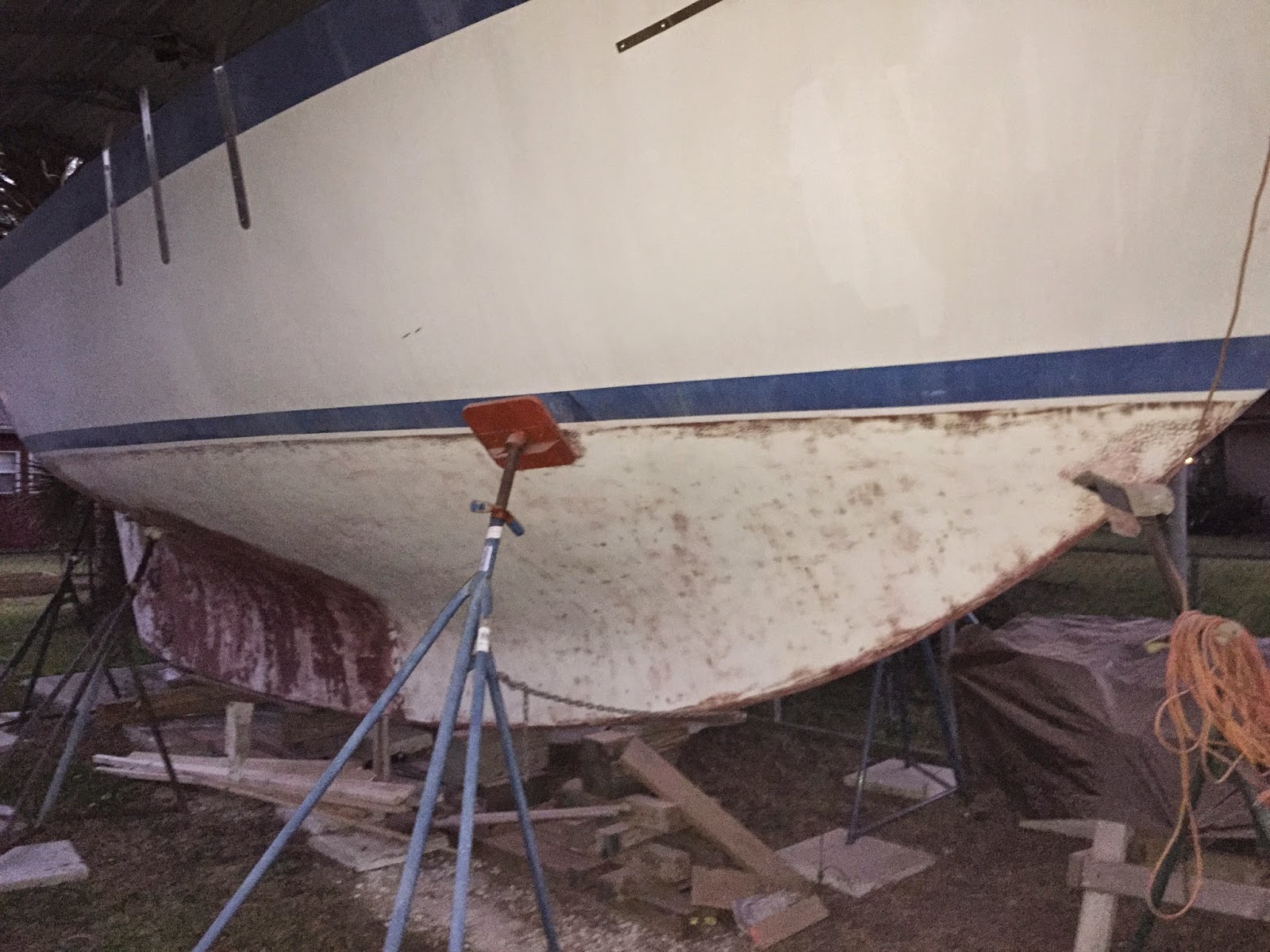
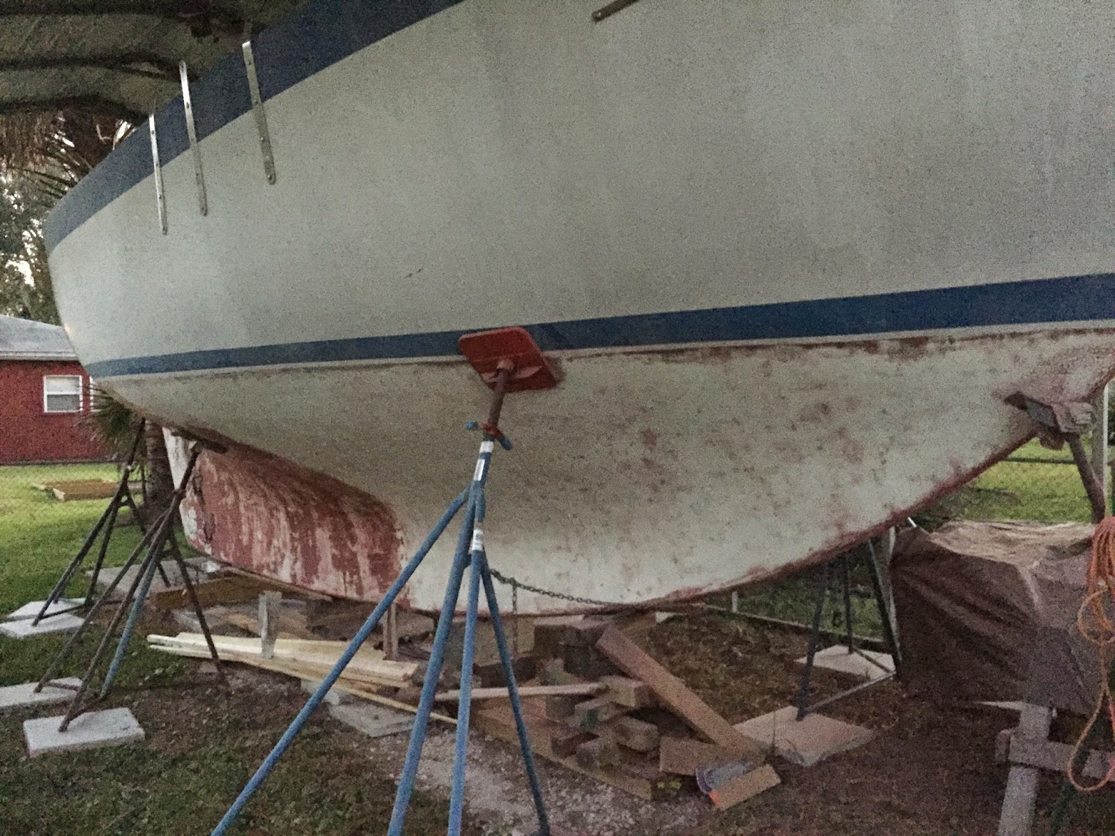
Saturday was the day to see whether the factory laid-up engine pan was to make it into the boat build.  I started by securing a length of string (plumb-bob string mind you, this is hi-tech stuff!), centered in the shaft log.  The string represents the center line of the propeller shaft, and serves as the reference point from which ostensibly the engine is built around.  But to build an engine around this datum, it is first necessary to install an engine bed to accept the engine.  In this case, I was going for the installation of a nice, factory laid-up engine pan (complete with gelcoat).


As you can see, the string is following the center of the shaft log as it is extended into the engine room. The string was pulled tight, and clamped to the forward portion of the engine pan.  


With the string, representing the propeller shaft, pulled tight and secured in its proper plane and positioning, I lowered the B-38 template I recently crafted into position.  With some cajoling of the template and use of some scrap wood, I was able to align the template in the same plane of the string. 


As can be seen below, the string intersects the aft portion of the engine template precisely in the position intended - at the gearbox output / shaft coupling - 3.1" below the bottom of the template.


Ensuring that the engine shared the string's (propeller shaft's) plane, the forward portion of the engine template also intersected the string at 3.1" below the engine template - in this case, the bottom of the engine template represents the bottom of the engine feet.


So with the engine template in position, it was time to talk myself into making this W32 engine pan work in the boat build.  To begin with , I looked over the port side of the template.  In the picture below, the immediate issue of the location of the port aft engine motor mount - represented here by pictured block of wood.  The engine feet have a width dimension at the base of roughly 2.5".  So the first issue is the port side's aft motor mount base interfering with the outboard side of the engine pan.


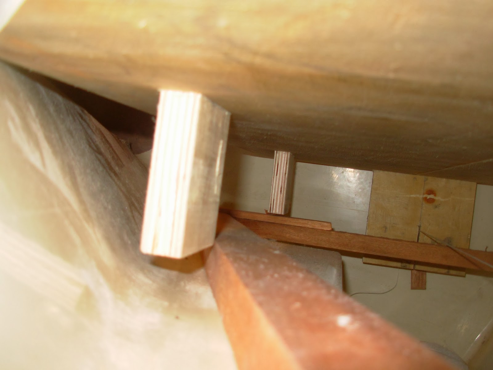
Moving to the port side's forward engine motor mount, the problem is obvious. The engine for which this pan was originally designed for - the Volvo MD-17, or similar from the '70s - has a wider dimension.  The Beta-38, although holding more horsepower, has a smaller plant dimension, and is more narrow at the forward end.  As a result of the narrow width the B-38, the motor mounts ended up well-inside the engine pan's bearing surface.  If this pan was to be used, I would need to accommodate  this void, and fabricate an extension of the pan's bearing surface to accept the forward motor mount.


Here is another shot of the port side's forward motor mount position, showing it falling inside of the more desired location.


Turning to the starboard side's aft motor mount position, the location here, like that of the port side, is too far outboard.  Again the base of the motor mount could not be seated properly due to the engine pan's outboard surface.


The starboard side's forward motor mount can be clearly see to be too far inboard, missing the pan's engine bearing surface - similar to the port side.


Here is another shot of the starboard side's forward motor mount (again, represented by the wood block in vertical alignment to that of the template), missing the engine pan's bearing surface.  With many of the questions I had now being answered by the alignment of the B-38 template over the engine pan, I had satisfied my curiosity and resigned to the decision to start fresh and build an engine bed customized to the B-38.  Agonizing over this decision was eliminated after further consultation with a friend and experienced builder.  The engine installation is still a ways out, so the B-38 may not ultimately be the engine that I install, or dimensions may change.  For now, however, the engine pan will be a no-go.  


Total Time: 2 Hrs.