Friday, November 15, 2013

Installation of Port V-Berth Bulkhead and Cabin Sole Layout


For a more thorough and professional explanation, see Lackey Sailing, LLC     


The morning of November 14th began with water washing and sanding the engine room bulkhead as well as the cabin sole floor timber just aft of the port primary bulkhead.


One of two cabin sole floor timbers, shown below, sits just aft of the port primary bulkhead, or mast bulkhead.  This floor timber was constructed of three laminations of 18mm meranti, glued and screwed.  The gluing consisted of West System epoxy thickened with cabosil.  Just forward of this mast bulkhead, I will eventually continue the floor timber, and build it out of 2 laminations of 18mm meranti. 


     As I prepared the previous day's epoxy work for eventual tabbing / additional epoxy bonding, Tim began work on finding the position for the head's forward bulkhead - plumb and perpendicular to the boat's center line.  I joined Tim in time for positioning and templating of the inboard section of this two-part bulkhead.  Cardboard is a great resource for templating bulkheads, partitions, cabin soles, etc.  


Tim making final scribe marks to the inboard portion of the head's forward bulkhead.


     Off the boat, Tim and transferred the template to a fresh sheet of 18mm meranti, and proceeded to cut out the inboard portion of the head's forward bulkhead.  Once cut, we carried it back onto the boat, solvent washed the edges that would exposed to the hull, and also solvent washed the portion of the hull and overhead that would be receiving this second part of this two-part bulkhead.  With all surfaces cleaned with solvent (acetone), I headed down to my shop and mixed a small batch of "neat" epoxy to paint onto the edges of the bulkhead that would be in contact with the boat's surfaces (hull, cabin trunk, and overhead).  After I had brushed on the straight epoxy, I mixed another batch of epoxy, this time thickened with cabosil.  Lines drawn onto the hull and overhead for both sides of this bulkhead provided a place for the thickened epoxy to be spread.  Tim and I then placed this second bulkhead into position, working the squeeze out along the joint between bulkhead and hull, and bulkhead and overhead.  We filled any small gaps between the two sections of this bulkhead and cleaned of the remaining epoxy mixture.


Looking aft from the v-berth.


Next, we turned to the cabin sole layout.  The Westsail 32 water tanks are still being built for owners today, though with a plastic material. The original stainless steel water tank dimensions have been recreated with plastic tanks.  I will be installing two of these water tanks, and so their height dimension dictated the cabin sole height.  The previous day, Tim and I set the forward cabin sole floor timber at the height I desired, and that would leave sufficient room for the water tanks (15" from the bilge floor to the bottom of the plywood substrate).  We now extended a string aft, and using a string level found where on the engine room bulkhead the bottom of the plywood substrate would eventually intersect.


After marking the location of the bottom surface of the plywood substrate onto the engine room bulkhead, we drew a horizontal line across the lower portion of the bulkhead, and installed a temporary cleat.  Using various length levels resting on the aft cleat and the forward cabin sole timber, we spanned them out onto the hull sides and made level marks - these marks indicated where the bottom surface of the cabin sole substrate would encounter the hull.  Limited to a 4' level, we then took measures off the string for the middle portion of the roughly 11' cabin sole.    


Once we had level marks along the port and starboard hull, indicating the bottom surface of the cabin sole's substrate, we began to fashion small knees out of polyisocyanurate foam.  We shaped the small knees to the hull form, set just below the cabin sole marks, and then hot-glued into place.


Pictured below are the cabin sole supports (knees) hot-glued into place. The aft pair were later to be scrapped, as I opted for another floor timber (a lamination of 4 pieces of 18 meranti.


Shown below is the glued and screwed 4-piece meranti lamination.  In this photo the floor timber has been shaped, painted with neat epoxy, and then set in thickened epoxy. This wrapped up the day's work.


Total Time: 8.5 Hrs.

Wednesday, November 13, 2013

Engine Room Bulkhead, Floor Timber , Head Forward Bulkhead


     For an even deeper accounting of the day's tasks:  Tim Lackey Sailing, LLC


     On Wednesday, the 13th of November, Tim Lackey and I turned our attention to the starboard and primary bulkheads once again, and to prepare for eventual tabbing.  I started off by water washing the epoxy work done the previous day: spray with water, scrub with a Scotchbrite pad and then towel off the excess water and amine blush.  Amine blush is a film that is left on cured epoxy, and that must be removed prior to any further epoxy work.


I finished this task by scuffing up the cured epoxy with 40-grit paper to prepare the surface for a mechanical epoxy bond (tabbing in the bulkheads).  The starboard primary bulkhead...


...and the port primary bulkhead.


As soon as I finished water washing and scuffing the cured epoxy, Tim moved into cutting the finished width of both bulkheads.  We purposefully left both bulkheads oversize (in the width dimension), as we planned to later come back and measure for the width, drop a plumb line, and then cut to this width.

The port bulkhead being cut by Tim Lackey...


...and the starboard bulkhead being cut to the proper width.


     Next, we turned our attention to the engine room bulkhead - the aft bulkhead of the main salon.  We began by referring to the Westsail construction manual - a manual designed for the "kit boat" customer...a manual going on 40 years!  The placement of the engine room bulkhead called for 10' 10" from the primary bulkheads.  Prior to our eventual placement of the new bulkhead, we discussed maximizing the salon space by tucking the bulkhead under the bridge deck.  However, we quickly realized that pushing the bulkhead toward the stern of the boat would have potentially left very little room for the engine installation.  Amazing how everything on a boat (everything!) is connected in some way.  We also checked the installation of the factory engine pan prior to final placement of the engine room bulkhead - hull #667 came with a factory prepared engine pan ready for installation.  I lugged the engine pan down into what would eventually become the engine room to determine fit.  After consulting with Tim, and specifically with respect to the Beta 38 engine, it became apparent that this pan was far too narrow for this engine.  The Westsail 32, a large number of them, came equipped with the Volvo MD-17.  The MD-17 has a smaller footprint that the Beta 38 (less horsepower as well), so while the engine pan was fine for the MD-17, it was not for the Beat 38.  We decided that it would be best to scrap the "gorgeous" engine pan, and opt for building a custom engine bed and pan for the Beta 38 installation.  

     So, back to the engine room bulkhead placement.  We made a series of marks 10' 10" from the primary bulkheads, placing these marks on the aft portion of the overhead. We checked for square of the overhead line (running athwartship, and perpendicular to the boat's center line) by taking diagonal measures from companionway to center line, on various points.  Once we determined we were square with this line, we dropped the line to the hull through a series of plum-bobs - there has apparently been quite a technological revolution in plum-bob technology, as we discovered the crude nature of my particular plum-bob tool!  The following photo shows two lines, one of which would eventually help to place an engine room bulkhead.  We carefully discussed and sorted out the advantages of an inch here and an inch there, though finally, and with peace of mind, settled on the location of the engine room bulkhead - not far from the Westsail manual...but enough to call it "custom!"


Next, we began the carving and fitting of the bulkhead template.  Tim often does this with sheets of cardboard saved from deliveries made to his shop.  He also works with door skin material in addition, as this more rigid product provides and excellent way in which to model the final installation.


Once we had completed the template, we laid it out on 3/4" (18mm) meranti, and used a jigsaw to cut out the bulkhead.


Here is the engine room bulkhead being fit in its new home.


Finally, we wet out the edges of the bulkhead with straight epoxy, and then followed that with a thickened mixture (cabosil), spreading out onto where the bulkhead edge would contact the hull.  We cleaned up the excess squeeze out, and then looked for the next to-do.


Turning out attention the cabin sole, the first order of business was to obtain the height cabin sole substrate - the dimension from the bilge to the underside of the plywood underlayment.  This dimension was more or less determined by the overall height of the water tanks - to be installed beneath the cabin sole.  I needed at least 14" of clearance in this dimension - the dimension become greater as one moves aft, due to the slopping of the bilge.  A quick phone chat with Bud Taplin confirmed the 14" clearance. In addition to the water tank dimension, I also had to take in account my overall height and what would feel comfortable to me walking inside the cabin.  Ultimately and after considerable consultation with Tim Lackey, I settled on a starting point of 14.5" from the bilge floor.  From here, there would 3/4" meranti as the sub-floor, and then a 1/4" finished teak floor.  This additional inch left 77" to the overhead.  The overhead would need to allow for an inch to be taken up by overheads beams and the finished overhead material.  In the end, I was left with 6' 2" of head room at the mast bulkheads, and increasingly taller dimension as one moved aft - comfortable to say the least.

Once, I was settled on the starting point dimension, Tim and I prepared 3 cardboard templates for what would become a floor timber at the mast bulkhead (the primary bulkhead), and can be seen in the photo below.  The pictures ran out here, but this floor timber was eventually laminated together (3 sections) - glued and screwed.  The floor timber was set in thickened epoxy (cabosil) in its pictured orientation.   


The last thing we did on this busy day, was to find the location of the forward bulkhead to the head (which is also the aft bulkhead to the V-berth).  After much discussion about elevating shower pans and heads, we settled on the placement of this bulkhead and then prepared the template that would be used to cut out the actual bulkhead from the meranti material.  This bulkhead would also be a two-part bulkhead, and I opted to cut a dado down the adjoining sections for a more seamless marriage of the two sections.  I finished the day by cutting the dado on one of the two sections that would make up this bulkhead.


Total Time: 9 Hrs.

Tuesday, November 12, 2013

Installation of Primary Bulkheads

(For a great explanation of the day's work, see Tim Lackey Sailing, LLC)


     For Tuesday, November 12th, the day's goal was for installation of the starboard and port primary bulkheads - those bulkheads that would define the forward portion of the main salon, and provide structural support for the mast and rigging.  The previous day, prior to pulling out the factory installed bulkheads, Tim and I patterned the bulkheads with rosin paper.  Now, with a full day to devote to these monster-sized bulkheads, we applied the patterns to new 3/4" meranti marine-grade plywood.   As can be seen in the following two photos, the port primary bulkhead was laid out onto two 4x8' sheets.  Very large bulkheads indeed, for this sailboat with an 11' beam.  


     The photo above shows the pattern laid out onto two sheets of meranti; the photo below is after the pattern was transferred to the meranti sheets.  The process for applying the pattern was relatively straight forward:  the lines applied to the circumference of the pattern, known widths taken from the hull to a point on the pattern, were then recreated onto the meranti sheets, using those known widths.  For example, the compass was set at 1.5" in width and run across the hull, scribing the line onto the paper pattern taped to the original bulkhead.  Now with the paper pattern laid out onto the new meranti material, that 1.5" compass width was recreated, and following the earlier line scribed onto the pattern, this line was then transferred to the new material.  The process requires a slow and steady approach, but is fairly easy.


The difficult part of the installation of these new bulkheads was their weight and massive size.  So large, in fact, that we could not fit the two-part port bulkhead through the companionway; nor could we "ease" the bulkheads through the cockpit sole.  So, back on the ground, we re-cut the two-part port bulkhead to produce two widths that could fit through the companionway.  With that problem solved, a new one popped up.  Originally, the plan was to glue and screw a "scab" section of meranti onto the two portions of the port bulkhead.  This "scab" section would be hidden within cabinetry inside the head, creating a nice finished look.  So, with the new location of the joint (closer to the center line of the boat), the "scab" board would now be too far inboard to be hidden within cabinetry.  I settled on the suggestion to join the two with biaxial cloth and epoxy resin.  In order to avoid having a length of 1708 biaxial cloth cure "proud" of the adjoining surfaces, I routed out a 1/8" section, roughly 3" wide, on both portions of the two-part port bulkhead, front and back.  The 1/8" deep channel will be wet-out with epoxy, and the biaxial cloth laid in to bond the two portions of the bulkhead together.  Tabbing around the circumference of the entire bulkhead will further strengthen and tie in the two-parts.  The 1/8" step down can be seen in the right side of the photo below.


Here is the outboard portion of the two-part port primary bulkhead.  The 1/8" deep channel can be seen as the darker, vertical section of the inboard portion of the panel.  Positioning of this bulkhead proved to be a slow, deliberate and thoughtful process.  With no good reference point within the hull - a very large void with sweeping curvy lines - it was important to get this first portion of the port bulkhead in the correction position, plum, and perpendicular within the boat.  All other installations will eventually draw off this panel, so its position became nearly overwhelmingly important :)  Hats off to Tim Lackey for being the "One Man...One Boat at a Time."  How he manages to place these large, heavy panels in boats with no horizontal surfaces, ALONE!, is quite impressive.  The two of us struggled through finding just the right orientation for these bulkheads, using hot glue and scrap blocks to assist with alignment.  In the end, we got what we were going for:  correct position, plum, and perpendicular!


Below, Tim holds the inboard section of the two-part port bulkhead.  The 1/8" deep channels can be seen aligned, and nearly ready to accept the biaxial cloth.


The photo below show the two-part port bulkhead tacked into place.  The process for tacking in the bulkheads includes wetting out the edges of the meranti plywood with "neat" epoxy (no thickening agents), and then applying a 3/4" thick bead of epoxy thickened with cabosil (fumed Silica).  Towards the end of the day, the epoxy had kicked (hardened).  Regardless, the tabbing would wait until the following day.


The starboard primary bulkhead gave Tim and I the same issues - to wide to pass through the companionway.  So, the altered the joint location, but this time opted for a "scab" piece.  The scab board would ultimately be hidden within cabinetry, so aesthetics would not be harmed.  The photo shows the starboard bulkhead tacked in and awaiting tabbing.


The following photo shows the scab piece on the forward face of the starboard two-part primary bulkhead.  Again, this scab piece will be hidden within cabinetry.


Finally, the forward face of the port two-part primary bulkhead.  The horizontal boards are temporary alignment braces.  These boards will be removed prior to tabbing and joining the two panels with a vertically aligned section of  1708 biaxial cloth.  


Total Time: 8 Hrs.

Monday, November 11, 2013

Removal of Original Bulkheads


     The serious work begins on Hull #667.  I have taken the week off from work and coordinated assistance from one of the best in boat restoration work - Tim Lackey of Lackey Sailing, LLC.  Since all of the boats furniture will be built off a few key reference points (primary bulkheads and cabin sole substrate), it became increasingly important that I have a skilled and experienced person on site to guide me through this critical phase.  So, for Monday the 11th of November, we started with removal of the 36 year old bulkheads...

     We started with just surveying the boat and finalizing our plan for the day.  This Westsail 32 came out of the factory as a kit (WSSK stamped) with the primary bulkheads.  There was some water damage in only a few places, prompting me to want to replace them.  However, the more concerning aspect of these bulkheads was the polyester used for the bulkhead tabbing - in many places one could pull off the tabbing by hand!  This was definitely not something I wanted on my boat.  Further, the primary bulkheads were not tabbed to the overhead - something that is standard practice in today's boat building yards.


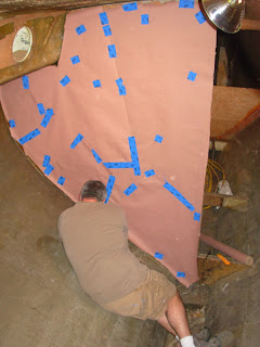
We moved onto patterning the existing bulkheads using a great technique being demonstrated in the following picture by Tim Lackey.  Using rosin paper, we covered the bulkhead so as to more or less replicate the existing shape.  The rosin paper is held on to the wood bulkhead by cutting out triangles and then placing tape over the paper and onto the wood surface.  Finally the outline is scribed with a compass, using a known dimension.  This pattern will be transferred to new sheets of 3/4" meranti plywood. 


     Patterning complete and full respirators donned, resembling an episode of Breaking Bad, we jumped in to removed the old bulkheads and generally prepare the boat to accept the new bulkheads.  I took to the reciprocating saw to cut out the bulkheads, flexing the blade to get as close to the hull surface as possible.  I then used a hammer and chisel to de-bond the old tabbing, and as I said before, some of the tabbing could be pulled up by hand.  Tim came behind me with the angle grinder, fitted with a 36 grit flap disk, and took the remaining uneven surfaces down to generally "fair" so as to be ready for a mechanical epoxy bonding of the new bulkheads.  Finally, we removed a factory installed engine bed as well - which nearly kicked both our butts!  


Now this is a "bare hull!"  Looking forward...in an empty boat.


Looking aft...in hull #667.


Chores


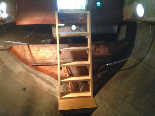
On Sunday, the 2nd of November, I finally got around to building a set of temporary stairs so that I could easily manage myself into and out of the cavernous interior.  It was a relaxing afternoon - cool temps, NPR Sunday programs...


I also took the time to pressure-wash the decks...it was just time for this chore.
Before...


...and after.


Total Time: 4.5 Hrs

Tuesday, March 5, 2013

Tiller's 6th Coat of Varnish


     Tuesday, March 5th, I took an hour out of a busy schedule to apply the tiller's 6th coat of varnish.  As always, I started with a light sanding , using 220 grit paper, of the cured 5th coat; wiped down the surface with a dry rag to remove as much dust as possible; and then lightly tacked off the surface with a solvent to remove and remaining residue and generally prepare the surface for its next coat of varnish.  The varnish used is Epifanes Clear High Gloss.

Pictured below, the tiller as it stood with the 5th coat ready to be lightly sanded.


The tiller after lightly sanding the 5th coat of varnish with 220 grit paper.


Finally, the 6th coat of varnish applied.


Total Time: 1 hour

Sunday, February 17, 2013

Tiller's 5th Coat of Varnish


     Sunday, February 17th,  taking a break from studies, I found an hour to apply the 5th coat of varnish to the newly crafted Westsail 32 tiller.  Like the previous coats, I followed the repetitive process for building up a suitable protective layer of varnish:  sand with 220 grit paper, wipe down with solvent, and then apply a coat of varnish (Epifanes Clear Gloss), thinned 10 to 15% with brushing thinner.

The 4th coat of varnish getting some sun prior to the sanding, below.


The tiller post-sanding, below.


...and after the 5th coat was applied, below.


Total Time: 1 hour