Monday, December 30, 2013

Engine Template (Beta 38)


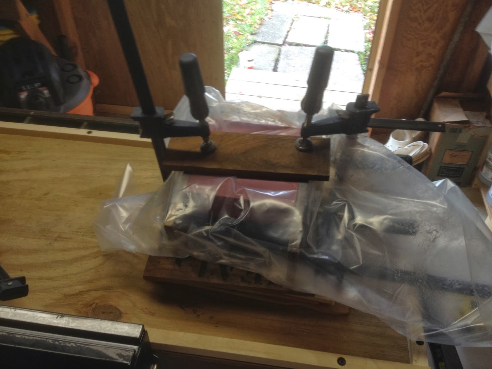
In the early evening I set out to release the recently laminated mast compression block from its clamps.  As can be seen below, there was ample squeeze-out of the thickened epoxy binding these laminations together.  Over the next couple days, I will take time to clean up the surfaces and then bond two layers of 1708 biaxial cloth to further prepare for its installation.  As fun as that was, the primary focus of today's work was to build a template of the proposed engine installation - Beta 38.


First order of business was to deconstruct the pallet I had around the shop over the last couple of months.  The pallet delivered a load of meranti, and while it was not cabinet or marine grade plywood, it was good enough for an engine template.  


I started by ripping the board down to a more manageable size, with a width sufficient enough for the maximum dimension of the engine.  Next I found what would be the center line of the shaft / gearbox output - I struck this line down the length of the board.  Next, I found the maximum starboard dimension from the center line at ~9" - happens to be the air filter.  Alternately, on the port side, I found the maximum dimension to be ~10.5" - the alternator.  So from here, I had the maximum width of the engine, and struck two lines the length of the board to represent these measurements.  I then rip cut the board along these two lines, arriving at a width representative of the engine's overall width.


I then found the location of the center lines of the flexible motor mounts, roughly 8 and 1/8" from the shaft / gearbox output center line, and struck two lines the length of the board.  From the aft end of the board I measured and found the locations of the centers of the four flexible motor mounts, and then pre-drilled the board to secure the four blocks shown below and which represent the motor mounts. The Beta motor mounts have a vertical adjustment of roughly 1" - from 65mm to 90mm.  The blocks used to represent the motor mounts were cut at 3", or a the mid-point of the adjustment range.  Using the mid-point of the adjustment range in the template process, after finding the engine's future resting place, would allow for fine-tuning of the engine's actual installation. 


The template with "motor mounts" attached.


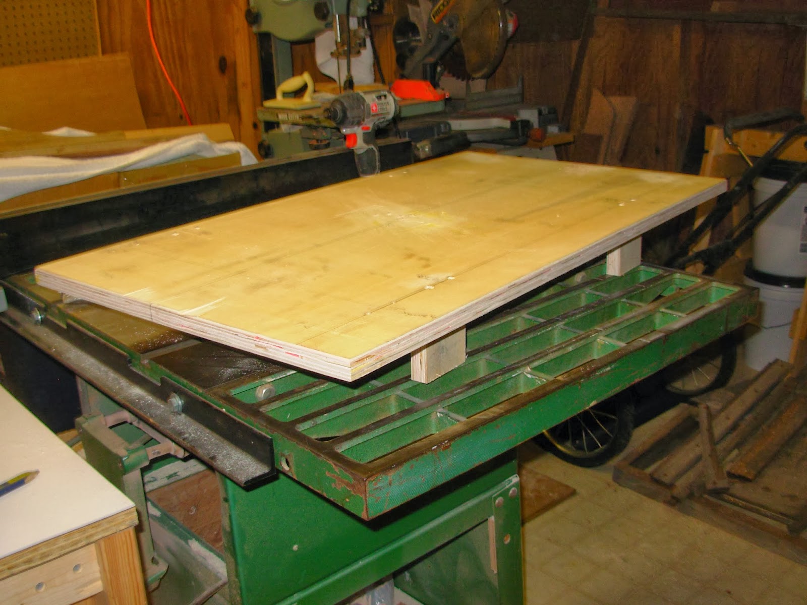
With the 'motor mounts' secured, I turned my attention to securing two blocks, forward and aft, to accept a string that will eventually be run from the shaft log and which will represent the shaft itself.  The center point of the shaft happen to be 3.1" below of the bottom surface of the engine template.  The bottom of the engine template represents the bottom surface of the engine feet - the engine feet are essentially angle irons which secure the engine to the flexible motor mounts.  It is worth noting here that the center point of the shaft / gearbox output is the datum from which all other measurements are taken.


With the engine template constructed, I'm looking forward to finding out if the factory engine pan is a "go" or "no go."


Total Time: 3 Hrs.

Sunday, December 29, 2013

Mast Compression Block, Interior Cabin Side Prep, Chores


After the excitement of the Christmas holiday, I took some time for a different kind of rest and relaxation - boat building.  Spending a "half-hour or so" in the boat, or the shop, often translates, literally, into hours!  Good times.  The goal for the short amount of time I had was to bond together the various laminations of the mast compression block, but quickly expanded into a few tasks that needed to be completed.  Before I went straight into bonding together the laminations of the compression block, forming one solid block, I brought the material into the boat for a dry fit.  I vacuumed up the fiberglass dust, from the last marathon round of interior surface prep, in and just around the targeted work area, solvent washed the keel underneath the floor timber at the mast bulkheads, and then placed the compression block in place for a dry fit.  The keel steps up roughly 5" inches at the forward end of the main salon - just aft of the mast bulkheads - and continues forward with a slight upward slope.  I placed the compression block on the keel and slide it underneath the floor timber.  The floor timber (a lamination of 4 18mm meranti boards) is installed level; however, due to the upward sloping keel, the void between the top of the mast compression block and the underside of the floor timber varied in dimension from front to back (sorry, no pic).  The aft portion of the void was roughly 1/4", and the forward portion roughly 3/16".  Most of the void would be filled with two layers of 1708 biaxial glass - to be installed prior to installation; and the balance of the void will be filled with colloidal silica-thickened epoxy used to bed the mast compression block in place.  The idea is to create structure from the mast step down to the keel, thereby transferring the load of the mast directly to the keel.  I will install a mast compression post  of Brazilian cherry (roughly 2" X 4") from the cabin overhead to the top of the floor timber - completing the mast step to keel structure.

The mast compression block consisted of four 6" X 6" solid fiberglass boards as the base, followed by a 6" square 8/4 teak block, and capped with a 1/2" purpleheart square.  The glass board will protect the compression block from lingering bilge moisture, and the density of the wood material will serve to provide great structure for transferring the mast load to the keel.


I painted out all surfaces with straight epoxy (no thickening agents), and then immediately came back with an application of epoxy thickened with colloidal silica applied to surfaces that would be bonded.


I wrapped the compression block laminations in plastic, applied 1/2" teak scrap to the exterior and clamped the block tightly while it cured.  The next step will be to apply two layers of 1708 biaxial cloth to help fill in most of the existing void between the top of the mast compression block and the underside of the floor timber.  As stated above, the balance of the void would be filled by thickened epoxy.


After the compression block was left to cure, I turned to cleaning out the smaller shop vac - the one dedicated to the boat.  The fiberglass dust does a quick job of clogging the vac's filter, to the point where it will fail to pick up large fragments.  This was a time-consuming chore, but necessary.

While I was in the boat dry-fitting the mast compression block, I noticed that I had only partially prepped the cabin sides.  This would be the last of the interior surface prep.  I started by removing a small amount of mahogany trim with a 1/4" wood chisel.  Most of this paneling had been removed a while back with a simple pry bar; however, a few stubborn areas remained.  Removing these well-bonded areas by hand would prove less difficult and time-consuming as opposed to using the sander.   With those areas at least 95% taken care of by the chisel, I set out to prep the port and starboard cabin sides.  Using my Porter Cable 7335 (outfitted with a 6" PSA pad), I made relatively quick work of the port side... 


...and the starboard side.  A few voids presented themselves through the prep sanding, and will be filled prior to applying the new wood paneling.


Before I closed up the boat, I brought the factory engine pan back down into the engine room for another test fit.  I was curious to see the fit of the engine pan after having just cut out the old engine beds.  It's a great looking engine pan, and sits very well in place.  The issue I am presented with is the engine's (Beta 38) oil pan and sump clearance, as well as getting access into the deepest part of the bilge - just below the engine pan. I believe I can overcome the engine clearance issue by bonding 3/4" G-10 boards on either side.  The G-10 boards would then be drilled and tapped to accept the motor mounts.  The added height would allow the engine's oil pan to clear the lower portion of the engine pan.  The second challenge: access to the bilge.  The roughly 12" long access just aft of the engine pan (see the "black hole") would be all I would have to get an arm down there.  Perhaps I could cut out a bit of the aft portion of the pan to allow better access...


Total Time: 4 Hrs.

Sunday, December 15, 2013

Finished Up Interior Surface Prep


Today I completed the interior sanding, surface prep, in anticipation of further bulkhead installations as well as furniture.  Over the coarse of the afternoon, I worked my way from the bow to the forward side of the mast bulkheads, sanding the hull, overhead, underneath of side decks, and bilge.  I was just way beyond having the energy to snap some photos of the work, but did have some photos available from day one of interior surface prep - showing the engine room.

Starboard engine room.


All sanding was done on the Porter Cable 7335 5" and 7336 6" random orbital sanders, using 40-grit psa pads.


Cockpit locker shown below, port engine room.


Parting shot of the stern.


Total Time: 5 Hrs.

Saturday, December 14, 2013

Mast Compression Block


Getting some errands out of the way earlier in the day, I managed to grab a couple hours in the shop preparing the mast compression block.  This block will eventually find its home underneath a floor timber at the primary/ mast bulkheads, and is designed to take and transfer the mast's load directly to the keel through a mast compression post spanning the vertical space from the overhead to the floor timber.  The compression block will be a lamination of 1/2" fiberglass sheet, as well as teak and purpleheart woods.  The fiberglass will be used as the bottom layers of the lamination for its obvious density and ability to take load, but also to avoid deterioration of the block as a result of potential water contact - any water draining from the chain lockers will run along this upper part of the bilge on its way back to an aft bilge pump.

I began by roughing up the factory-finished surfaces of the 1/2" fiberglass sheet.  The pink-colored board you see in the picture below began as a fairly bright shade of red.  Abrading the smooth surface will promote a good bond in the laminating process.  Next, I divided the sheet into four 6" blocks.


Since fiberglass is so harsh on the blades, I put an aging, sacrificial blade in the table saw prior to cutting the 1/2" sheet.


I took the four 6" X 6" blocks up into the boat to take some preliminary measurements.  After stacking the four blocks on top of one another, I slide them underneath the floor timber, resting on the keel, and took a measurement aft of the floor timber...


...and on the forward side of the floor timber.


The measurements varied from roughly 2 3/4" forward to 2 3/8" on the aft side.  This variance was due to the port bulkhead "hanging" a bit lower than the floor timber that rested against it.  The void between the top of the fiberglass stack and the underside of the floor timber would be taken up by hardwoods capable of taking substantial compression force.  The species I have decided to use are teak and purpleheart.  I would of liked to have had a single block of teak to use in conjunction with the fiberglass lamination, but no such luck.  The 1/2" sheet of purpleheart will be placed on top of the teak and, having a modulus of rupture measure of 22,000 pounds force per square inch, would provide great strength in the overall mast compression block lamination.


The mast compression block as it will be laminated, and to be placed underneath the floor timber to span the space between the underside of the floor timber and the keel.


The compression block measures about 4.5" in thickness.  Epoxy, thickened with cabosil, will be used to set the mast compression block in place and to fill any small voids.  Next step will be to epoxy bond the lamination together to create one, solid block.  The block will also be completely sealed with epoxy as it is placed in its final resting position.


Total Time: 2.5 Hrs