After the excitement of the Christmas holiday, I took some time for a different kind of rest and relaxation - boat building. Spending a "half-hour or so" in the boat, or the shop, often translates, literally, into hours! Good times. The goal for the short amount of time I had was to bond together the various laminations of the mast compression block, but quickly expanded into a few tasks that needed to be completed. Before I went straight into bonding together the laminations of the compression block, forming one solid block, I brought the material into the boat for a dry fit. I vacuumed up the fiberglass dust, from the last marathon round of interior surface prep, in and just around the targeted work area, solvent washed the keel underneath the floor timber at the mast bulkheads, and then placed the compression block in place for a dry fit. The keel steps up roughly 5" inches at the forward end of the main salon - just aft of the mast bulkheads - and continues forward with a slight upward slope. I placed the compression block on the keel and slide it underneath the floor timber. The floor timber (a lamination of 4 18mm meranti boards) is installed level; however, due to the upward sloping keel, the void between the top of the mast compression block and the underside of the floor timber varied in dimension from front to back (sorry, no pic). The aft portion of the void was roughly 1/4", and the forward portion roughly 3/16". Most of the void would be filled with two layers of 1708 biaxial glass - to be installed prior to installation; and the balance of the void will be filled with colloidal silica-thickened epoxy used to bed the mast compression block in place. The idea is to create structure from the mast step down to the keel, thereby transferring the load of the mast directly to the keel. I will install a mast compression post of Brazilian cherry (roughly 2" X 4") from the cabin overhead to the top of the floor timber - completing the mast step to keel structure.
The mast compression block consisted of four 6" X 6" solid fiberglass boards as the base, followed by a 6" square 8/4 teak block, and capped with a 1/2" purpleheart square. The glass board will protect the compression block from lingering bilge moisture, and the density of the wood material will serve to provide great structure for transferring the mast load to the keel.

I painted out all surfaces with straight epoxy (no thickening agents), and then immediately came back with an application of epoxy thickened with colloidal silica applied to surfaces that would be bonded.

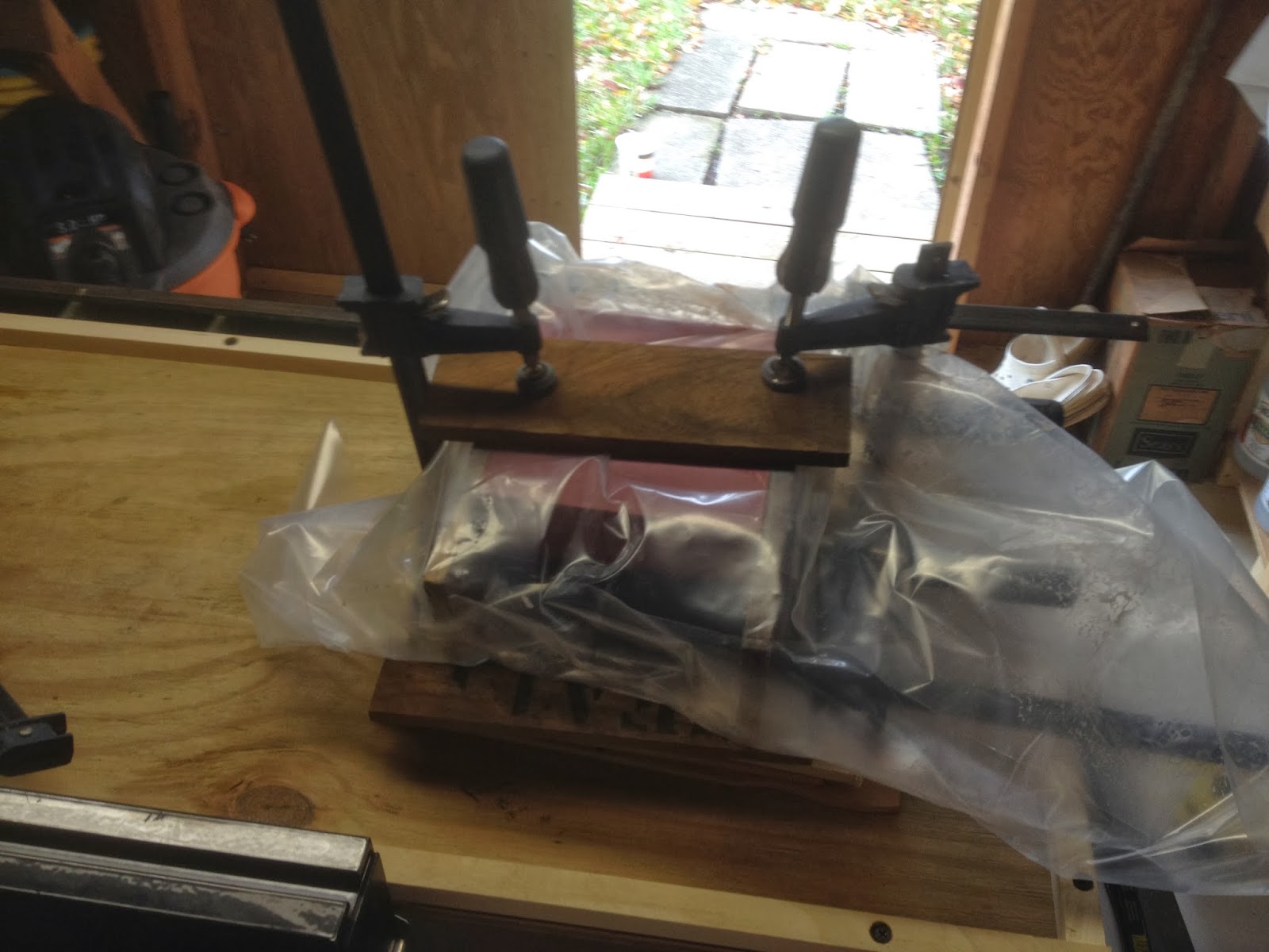
I wrapped the compression block laminations in plastic, applied 1/2" teak scrap to the exterior and clamped the block tightly while it cured. The next step will be to apply two layers of 1708 biaxial cloth to help fill in most of the existing void between the top of the mast compression block and the underside of the floor timber. As stated above, the balance of the void would be filled by thickened epoxy.
After the compression block was left to cure, I turned to cleaning out the smaller shop vac - the one dedicated to the boat. The fiberglass dust does a quick job of clogging the vac's filter, to the point where it will fail to pick up large fragments. This was a time-consuming chore, but necessary.
While I was in the boat dry-fitting the mast compression block, I noticed that I had only partially prepped the cabin sides. This would be the last of the interior surface prep. I started by removing a small amount of mahogany trim with a 1/4" wood chisel. Most of this paneling had been removed a while back with a simple pry bar; however, a few stubborn areas remained. Removing these well-bonded areas by hand would prove less difficult and time-consuming as opposed to using the sander. With those areas at least 95% taken care of by the chisel, I set out to prep the port and starboard cabin sides. Using my Porter Cable 7335 (outfitted with a 6" PSA pad), I made relatively quick work of the port side...

...and the starboard side. A few voids presented themselves through the prep sanding, and will be filled prior to applying the new wood paneling.

Before I closed up the boat, I brought the factory engine pan back down into the engine room for another test fit. I was curious to see the fit of the engine pan after having just cut out the old engine beds. It's a great looking engine pan, and sits very well in place. The issue I am presented with is the engine's (Beta 38) oil pan and sump clearance, as well as getting access into the deepest part of the bilge - just below the engine pan. I believe I can overcome the engine clearance issue by bonding 3/4" G-10 boards on either side. The G-10 boards would then be drilled and tapped to accept the motor mounts. The added height would allow the engine's oil pan to clear the lower portion of the engine pan. The second challenge: access to the bilge. The roughly 12" long access just aft of the engine pan (see the "black hole") would be all I would have to get an arm down there. Perhaps I could cut out a bit of the aft portion of the pan to allow better access...

Total Time: 4 Hrs.
Your engine is going to sit right on top of the deepest part of the bilge? That's going to take some interesting engineering to make sure it stays dry. I'm a fan of keeping the bilge as dry as possible and I'm curious how you'll accomplish it. Perhaps an impeller pump connected with a Vetus bilge water/oil separator could take care of that along with proper ventilation. There will be debris coming off the engine but you can always vacuum it on occasion (assuming the bilge pump hose end can come out easily) to prevent anything from getting into that cavernous abyss. Nice to see such progress Brian.
ReplyDeleteThanks Tony. The engine pan, as per Bud, is installed adjoining the aft of the engine bulkhead...so, by location of the engine pan, the engine is installed over the aft portion of the bilge - though not at the deepest portion of the bilge. It should be just where your engine is located. The pan provides separation between the engine and the moisture laden bilge, reducing condensation forming on the engine belly. Without the engine pan, I would still install some sort of pan (plywood glassed in) to provide a catch for slippery tools and a moisture break. -Brian
ReplyDeleteOn our Westsail #731 we also have a pan that sits over the bilge. This fiberglass pan sits over and sort of seals up the deepest part of the bilge. So if I drop something it falls into the pan never reaching the bilge. Unless its small like a screw and sneaks past the 1/2" drain hole.
ReplyDeleteI like your blog - very interesting to watch you build this fine yacht.
Appreciate that, Harbinger.
Delete